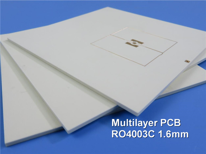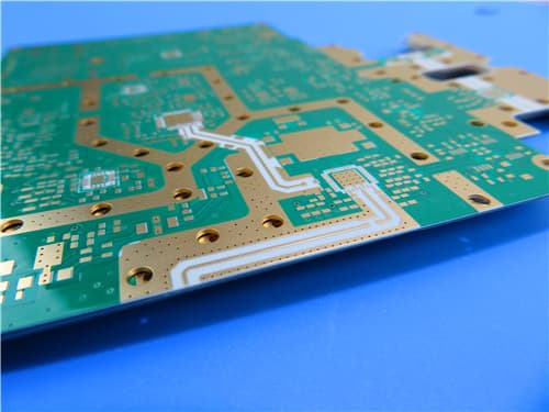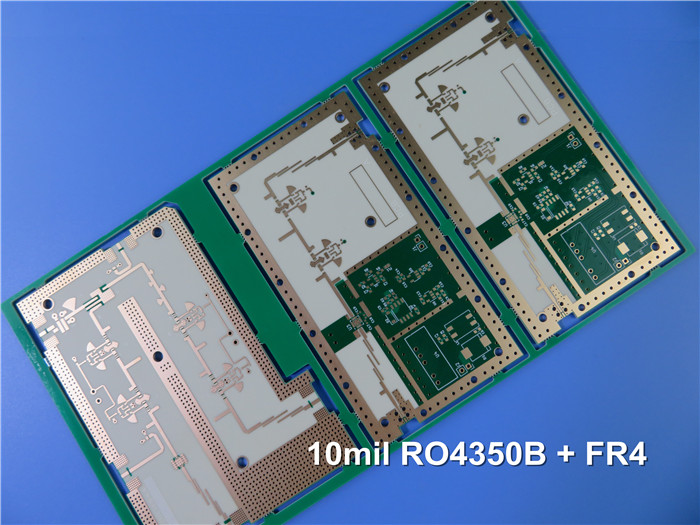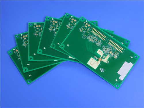
* PCBs are custom-made, picture & parameters for reference
8-Layer Hybrid PCB - RO4003C (8mil) and S1000-2M with Blind Vias and Resin Plugged Holes
(Note: Printed Circuit Boards are custom-made products. Images and parameters are for reference only.)
1. Introduction to 8-Layer Hybrid PCB
This 8-layer hybrid PCB combines Rogers RO4003C hydrocarbon ceramic laminates on the outer layers (TOP and BOTTOM) with Shengyi S1000-2M high-performance FR-4 material in the inner layers. The RO4003C material provides superior high-frequency performance with low dielectric loss (Df 0.0027) and stable dielectric constant (DK 3.38), making it ideal for RF and microwave signal transmission. The S1000-2M material offers excellent thermal reliability with TG185 and high electrical strength for digital and power layers.
This hybrid construction leverages the strengths of both materials: Rogers RO4003C for high-frequency signal integrity on outer layers, and Shengyi S1000-2M for cost-effective, high-reliability inner layers. The board features blind vias (L1-L2 and L7-L8) and resin plugged holes (0.2mm, 0.25mm, 0.35mm) for enhanced routing density and reliability.
2. PCB Construction Details
| Item | Specification |
|---|---|
| Base material | Hybrid: TOP/BOTTOM RO4003C (0.203mm/8mil) + Inner S1000-2M (FR-4, TG170) |
| Layer count | 8-layer |
| Board dimensions | 273mm x 185mm = 1 PCS (including panel edge), ±0.15mm |
| Finished board thickness | 1.6mm (Pressed thickness: 1.579mm) |
| Outer copper weight | 1 oz (35 μm) |
| Inner copper weight | 0.5 oz (17 μm) / 1 oz (35 μm) hybrid |
| Via plating thickness | 20 μm |
| Blind vias | L1-L2 and L7-L8 |
| Resin plugged holes | 0.2mm, 0.25mm, 0.35mm |
| Surface finish | ENIG (Electroless Nickel Immersion Gold) |
| Top Solder Mask | Green |
| Bottom Solder Mask | Green |
| Top Silkscreen | White |
| Bottom Silkscreen | White |
| 100% Electrical test | Used prior to shipment |
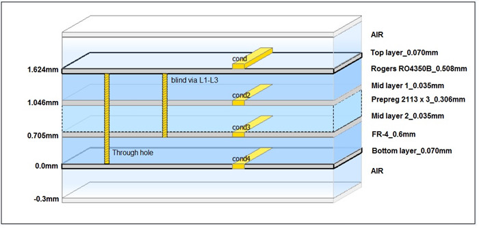
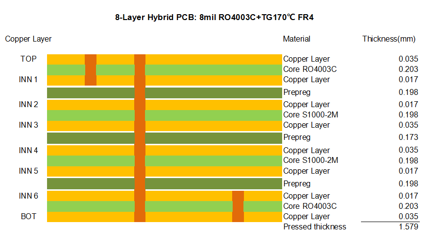
3. PCB Stackup (8-Layer Hybrid Structure)
| Layer | Material | Thickness (mm) |
|---|---|---|
| TOP | Copper Layer | 0.035 |
| Core RO4003C | 0.203 | |
| INN 1 | Copper Layer | 0.017 |
| Prepreg | 0.198 | |
| INN 2 | Copper Layer | 0.017 |
| Core S1000-2M | 0.198 | |
| INN 3 | Copper Layer | 0.035 |
| Prepreg | 0.173 | |
| INN 4 | Copper Layer | 0.035 |
| Core S1000-2M | 0.198 | |
| INN 5 | Copper Layer | 0.017 |
| Prepreg | 0.198 | |
| INN 6 | Copper Layer | 0.035 |
| Core RO4003C | 0.203 | |
| BOT | Copper Layer | 0.035 |
| Pressed Thickness | 1.579 | |
4. Rogers RO4003C - High Frequency Circuit Material
RO4000 hydrocarbon ceramic laminates are designed to offer superior high frequency performance and low cost circuit fabrication. The result is a low loss material which can be fabricated using standard epoxy/glass (FR-4) processes offered at competitive prices.
RO4000 material possesses the properties needed by designers of RF microwave circuits and matching networks and controlled impedance transmission lines. Low dielectric loss allows RO4000 series material to be used in many applications where higher operating frequencies limit the use of conventional circuit board laminates. The temperature coefficient of dielectric constant is among the lowest of any circuit board material, and the dielectric constant is stable over a broad frequency range.
Key Features of RO4003C:
Dielectric Constant (DK): 3.38 ± 0.05 at 10GHz
Dissipation Factor (Df): 0.0027 at 10GHz
Thermal Coefficient of DK: +40 ppm/°C
TG: >280°C — Excellent thermal stability
CTE X/Y: 11/14 ppm/°C — Matched to copper
CTE Z: 46 ppm/°C — Reliable plated through holes
Thermal Conductivity: 0.71 W/m/°K
Moisture Absorption: 0.06%
UL 94 V-0 Flammability Rating
5. Shengyi S1000-2M - High-Performance FR-4 Material
S1000-2M is a high-performance modified epoxy FR-4 material designed for high layer count applications requiring excellent thermal reliability and electrical performance. It features a TG of 185°C (DMA) and exhibits superior CAF resistance, thermal stability, and lead-free process compatibility.
Key Features of S1000-2M:
TG (DMA): 185°C — Excellent thermal reliability
Dielectric Constant (1GHz): 4.6
Dissipation Factor (1GHz): 0.018
Volume Resistivity: >10⁶ MΩ·cm
CTE Z-axis: 41 ppm/°C (Before Tg), 208 ppm/°C (After Tg)
CTE Z-axis (50-260°C): 2.4%
Td (5% weight loss): 355°C
T260: >60 min, T288: >30 min, T300: >15 min
Water Absorption: 0.08%
UL 94 V-0 Flammability Rating
6. Key Features of This Hybrid PCB
Hybrid Construction — RO4003C for high-frequency outer layers + S1000-2M for reliable inner layers
RO4003C: Low Dk (3.38) & Low Df (0.0027) — Superior high-frequency performance for RF/microwave signals
S1000-2M: TG185 & High Reliability — Excellent thermal and mechanical properties for digital/power layers
Blind Vias (L1-L2, L7-L8) — Enhanced routing density for complex designs
Resin Plugged Holes (0.2/0.25/0.35mm) — Improved via reliability and planarity
ENIG Surface Finish — Excellent solderability, corrosion resistance, wire bondability
1.6mm Finished Thickness — Standard thickness for robust mechanical stability
Lead-Free Process Compatible — Suitable for environmentally friendly manufacturing
7. Typical Applications
RF and Microwave Circuits
High-Speed Digital Systems
Telecommunications Infrastructure and Base Stations
Radar Systems and Phased Array Antennas
Satellite Communications and Avionics
High-Performance Computing and Networking Equipment
Automotive Radar and Advanced Driver Assistance Systems (ADAS)
8. RO4003C Typical Properties (Data Sheet)
| Property | Typical Value | Direction | Unit | Condition | Test Method |
|---|---|---|---|---|---|
| Dielectric Constant, εr Process | 3.38 ± 0.05 | Z | — | 10 GHz/23°C | IPC-TM-650 2.5.5.5 Clamped Stripline |
| Dielectric Constant, εr Design | 3.55 | Z | — | 8 to 40 GHz | Differential Phase Length Method |
| Dissipation Factor tan, δ | 0.0027 | Z | — | 10 GHz/23°C | IPC-TM-650 2.5.5.5 |
| Thermal Coefficient of εr | +40 | Z | ppm/°C | -50°C to 150°C | IPC-TM-650 2.5.5.5 |
| Volume Resistivity | 1.7 × 10¹⁰ | — | MΩ·cm | COND A | IPC-TM-650 2.5.17.1 |
| Surface Resistivity | 4.2 × 10⁹ | — | MΩ | COND A | IPC-TM-650 2.5.17.1 |
| Electrical Strength | 31.2 (780) | Z | KV/mm (V/mil) | 0.51mm (0.020") | IPC-TM-650 2.5.6.2 |
| Tensile Modulus | 19,650 (2,850) | X | MPa (ksi) | RT | ASTM D638 |
| Tensile Strength | 139 (20.2) | X | MPa (ksi) | RT | ASTM D638 |
| Flexural Strength | 276 (40) | — | MPa (kpsi) | — | IPC-TM-650 2.4.4 |
| Dimensional Stability | <0.3 | X,Y | mm/m (mils/inch) | after etch + E2/150°C | IPC-TM-650 2.4.39A |
| CTE (X-axis) | 11 | X | ppm/°C | -55 to 288°C | IPC-TM-650 2.4.41 |
| CTE (Y-axis) | 14 | Y | ppm/°C | -55 to 288°C | IPC-TM-650 2.4.41 |
| CTE (Z-axis) | 46 | Z | ppm/°C | -55 to 288°C | IPC-TM-650 2.4.41 |
| Tg | >280 | — | °C TMA | A | IPC-TM-650 2.4.24.3 |
| Td | 425 | — | °C TGA | — | ASTM D3850 |
| Thermal Conductivity | 0.71 | — | W/m/°K | 80°C | ASTM C518 |
| Moisture Absorption | 0.06 | — | % | 48 hrs immersion, 50°C | ASTM D570 |
| Density | 1.79 | — | g/cm³ | 23°C | ASTM D792 |
| Copper Peel Strength | 1.05 (6.0) | — | N/mm (pli) | after solder float, 1 oz EDC | IPC-TM-650 2.4.8 |
| Flammability | N/A | — | — | — | UL 94 |
| Lead-Free Process Compatible | Yes | — | — | — | — |
9. S1000-2M Typical Properties (Data Sheet)
| Property | Spec | Typical Value | Condition | Unit |
|---|---|---|---|---|
| Tg (DMA) | ≥180 | 185 | — | °C |
| Flammability | V-0 | V-0 | C-48/23/50, E-24/125 | Rating |
| Volume Resistivity | ≥10⁶ | 6.79×10⁷ | After moisture resistance | MΩ·cm |
| Volume Resistivity | ≥10³ | 2.19×10⁸ | E-24/125 | MΩ·cm |
| Surface Resistivity | ≥10⁴ | 3.16×10⁶ | After moisture resistance | MΩ |
| Surface Resistivity | ≥10³ | 2.24×10⁷ | E-24/125 | MΩ |
| Arc Resistance | ≥60 | 133 | D-48/50+D-0.5/23 | S |
| Dielectric Breakdown | ≥40 | 45kV+NB | D-48/50+D-0.5/23 | kV |
| Dielectric Constant (1GHz) | — | 4.6 | C-24/23/50 | — |
| Dielectric Constant (1MHz) | ≤5.4 | 4.9 | C-24/23/50 | — |
| Dissipation Factor (1GHz) | — | 0.018 | C-24/23/50 | — |
| Dissipation Factor (1MHz) | ≤0.035 | 0.015 | C-24/23/50 | — |
| Thermal Stress | >10s No Delam | >100s No Delam | 288°C, solder dip | — |
| Peel Strength (1 Oz) | ≥1.05 | 1.3 | 288°C/10s | N/mm |
| Flexural Strength (LW) | ≥415 | 567 | — | MPa |
| Flexural Strength (CW) | ≥345 | 442 | — | MPa |
| Water Absorption | ≤0.5 | 0.08 | D-24/23 | % |
| CTE Z-axis (Before Tg) | ≤60 | 41 | — | ppm/°C |
| CTE Z-axis (After Tg) | ≤300 | 208 | — | ppm/°C |
| CTE Z-axis (50-260°C) | ≤3.0 | 2.4 | — | % |
| Td (5% weight loss) | ≥340 | 355 | — | °C |
| T260 | ≥30 | 60 | TMA | min |
| T288 | ≥5 | 30 | TMA | min |
| T300 | ≥2 | 15 | TMA | min |
| CTI | PLC3 | PLC3 (200V) | IEC60112 Method | V |
10. Quality Assurance
Type of artwork supplied: Gerber RS-274-X
Accepted standard: IPC-Class-2
Availability: Worldwide
100% Electrical test prior to shipment
Get a Quick Quote
Fill in the form below and our engineers will reply within 24 hours with technical specifications and pricing for 8-Layer Hybrid PCB - RO4003C and S1000-2M.
.jpg)